|
MCU
|
ESP32 DevKit V1(ESP-WROOM-32)
|
|
IDE
|
VSC + ESP-IDF
|
|
목표
|
ESP32 DevKit V1의 LED를 ON-OFF
|
1. ESP-IDF
View - Command Palette

blink - Create project using example blink


LED GPIO 설정
#define BLINK_GPIO 2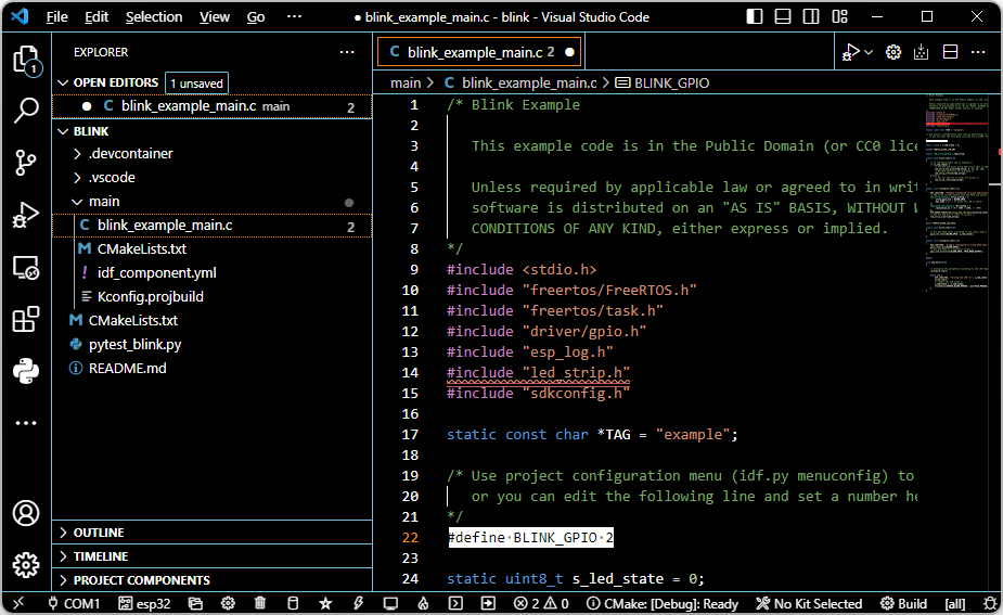
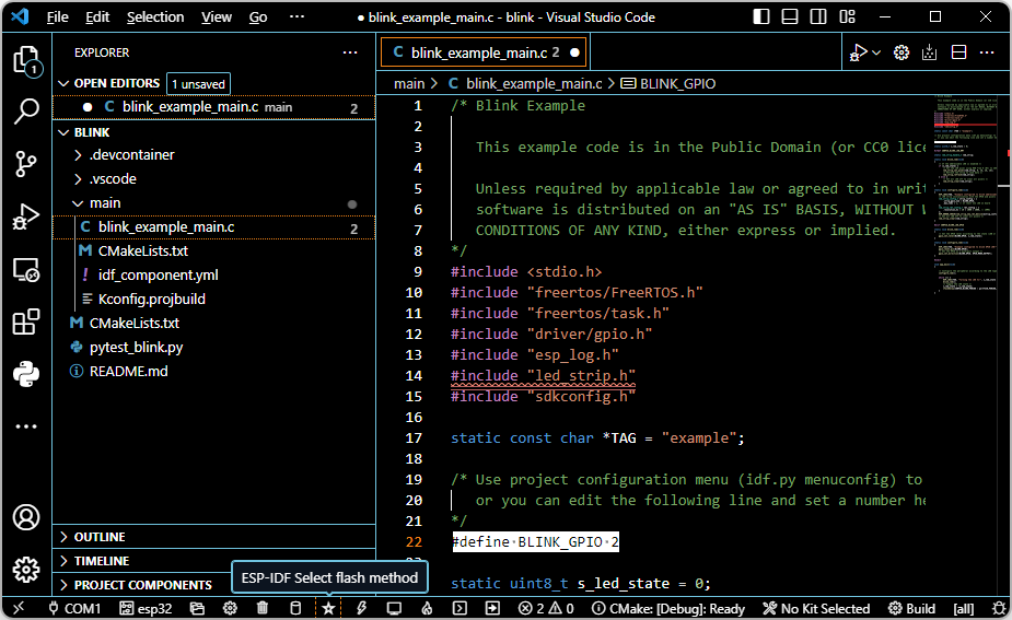
flash method - UART

serial port - COM3


Build - 에러남

다음과 같이 c_cpp_properties.json를 수정
{
    "configurations": [
        {
            "name": "ESP-IDF",
            "compilerPath": "E:\\WORK\\P_ESP32\\.espressif\\tools\\xtensa-esp32-elf\\esp-12.2.0_20230208\\xtensa-esp32-elf\\bin\\xtensa-esp32-elf-gcc.exe",
            "cStandard": "c11",
            "cppStandard": "c++17",
            "includePath": [
                "${config:idf.espIdfPath}/components/**",
                "${config:idf.espIdfPathWin}/components/**",
                "${config:idf.espAdfPath}/components/**",
                "${config:idf.espAdfPathWin}/components/**",
                "${workspaceFolder}/**"
            ],
            "browse": {
                "path": [
                    "${config:idf.espIdfPath}/components",
                    "${config:idf.espIdfPathWin}/components",
                    "${config:idf.espAdfPath}/components/**",
                    "${config:idf.espAdfPathWin}/components/**",
                    "${workspaceFolder}"
                ],
                "limitSymbolsToIncludedHeaders": false
            },
            "configurationProvider": "ms-vscode.cmake-tools",
            "compileCommands": "${workspaceFolder}/build/compile_commands.json"
        }
    ],
    "version": 4
}
Build - 에러 없어짐

Flash


'ESPRESSIF > ESP32' 카테고리의 다른 글
| ESP32 개발 환경 구축(2) - VSC + ESP-IDF 설치 (0) | 2025.03.20 |
|---|---|
| ESP32 개발(Arduino IDE) - Wifi 연결 (0) | 2025.03.20 |
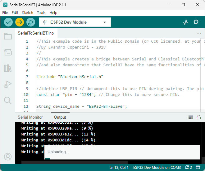
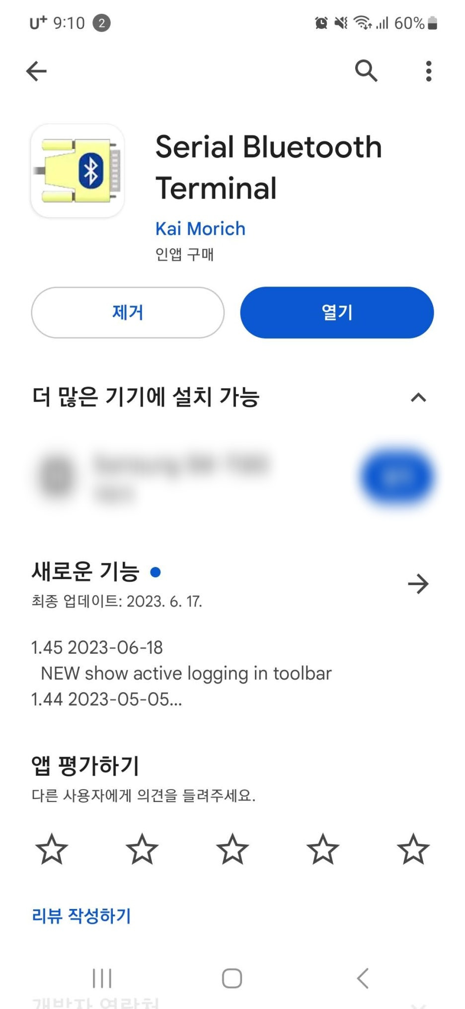
| ESP32 개발(Arduino IDE) - Bluetooth Serial (0) | 2025.03.19 |
| ESP32 개발(Arduino IDE) - RGB LED Strip 구동 (0) | 2025.03.19 |
| ESP32 개발(Arduino IDE) - LED 점멸 (0) | 2025.03.19 |